In a previous article we learned about the purpose of CAD software in engineering and design. CAD software allows engineers to design components, systems, and products. While CAD is heavily used to design the product, the final product still requires manufacturing. For an object to be manufactured by a 3D printer, Slicer Software must be used.
Manufacturing is how engineers turn computer designs into real-life physical objects. In order to do this, companies must use manufacturing equipment and machines that can create a physical object from a computer design. Examples of manufacturing equipment include CNC machines, laser engravers, and even simple hand tools.

3D Printing is also a very common form of manufacturing. While most companies use 3D printing to create models of their products, others use specialized 3D printing to build the final version of their innovations.
But how does a simple computer CAD design become a physical object? How does a 3D printer know how to print any design? What steps do we have to take to 3D print physical objects that match the models on our screens?
To answer these questions and understand the full process of 3D printing a computer design, we must first understand each common file type used in 3D printing.
3D Model File Types
STL Files
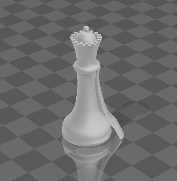
STL files are the most commonly used files to store 3D designs for 3D printing. These files store the mesh geometry of the design in the form of triangular surfaces. While the use of triangular surfaces may seem limited, any shape imaginable can be created in this file format.
For example, circles can be represented in an STL File, just not real circles. Theoretically, a circle has no vertices, as it’s a curve. However, it’s impossible to represent a shape with no vertices in the physical world. For this reason, while STL files show shapes that look like circles, it’s actually countless triangles put together to create what looks to be a circle.
Many hobbyists use STL files to print because of its storage efficiency compared to alternative file formats.
OBJ Files
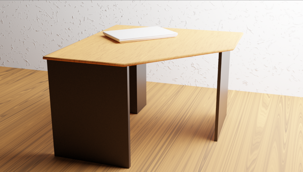
OBJ files are similar to STL files, as both file formats store a 3D design or model from a CAD or 3D modeling software. However, while STL files store the geometry of an object, OBJ files can store other information relating to the model. For example, OBJ files can store the model’s colors, textures, materials, and more. For this reason, OBJ and other similar file types are often used when making animations or character models.
While OBJ files store more information than STL files, we’ll soon see that STL files and OBJ files share the same role in 3D printing. Color, texture, and materials are important when exporting a model for animation, however, in simple 3D printing, these properties won’t be beneficial.
STEP or STP Files
STEP files are also very similar to STL files, both file types store the geometry of an object without storing any other properties like color or surface material. However, STEP files store more information about a model’s geometry. More specifically, STEP files can store more information about curves than STL files can.
Companies often use STEP files when manufacturing because it stores more information than STL files. However, this file type still comes with some disadvantages. STEP files store more information than STL files, but are also substantially less efficient in storage methods. For this reason, STL files are often favored over STEP files when it comes to rapid prototyping and in our case, 3D printing.
What are Native File Formats?
All the file types we talked about above are neutral file types. This means these files can be exported and imported universally across different software programs. If someone creates a CAD model on SketchUp and export it as an STL file, they can import that file onto Fusion 360, or Solidworks, or almost any other 3D CAD software.
Native file types don’t have this ability. Files exported in these formats can only be opened and edited on the CAD software that provided the file type. Let’s go back to our previous example and try to imagine what would happen if we exported a SketchUp model as a native sketchup file. If this happened, we wouldn’t be able to open this file in Fusion 360, or any other CAD software. Instead, we must export the model as a neutral file type.
G-code
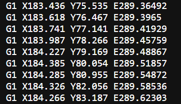
All file formats shown above, both neutral and native, showcase a model’s mesh geometry. However, 3D printers can’t print an object just from a geometric mesh. In order for a 3D printer to know what movements and actions it needs to take to print an object, it requires a list of “instructions”.
These instructions are essentially what G-code is. G-code is stored as a series of coded instructions that 3D printers can read and act on. Most often, G-code tells a 3D printer what movements to make in order to print the object in the correct dimensions and shape.
While movements make up most of its abilities, G-code can also control bed and nozzle temperature, filament extrusion and intrusion, auto-leveling the bed, and more. Almost every action that a 3D printer makes is because of G-code.
Slicer Software
What does a Slicer Software do?
The idea of G-code may seem overwhelming, as even very simple objects will have hundreds and thousands of lines of G-code. It would be a pain to have to input each and every G-code instruction into the 3D printer, just by looking at the model. This is why we have slicer software.
Slicer software are one of the most important parts of 3D printing a model. A slicer software takes the 3D model file that was inputed, and turns it into G-code for a printer to understand. In more simple terms, it takes the model, and creates a series of instructions from that model. The 3D printer then uses that series of instructions (G-code) to print the desired model. Because of slicer software, we don’t have to manually input each and every G-code instruction into the printer.
What does a Slicer Software “Slice”?
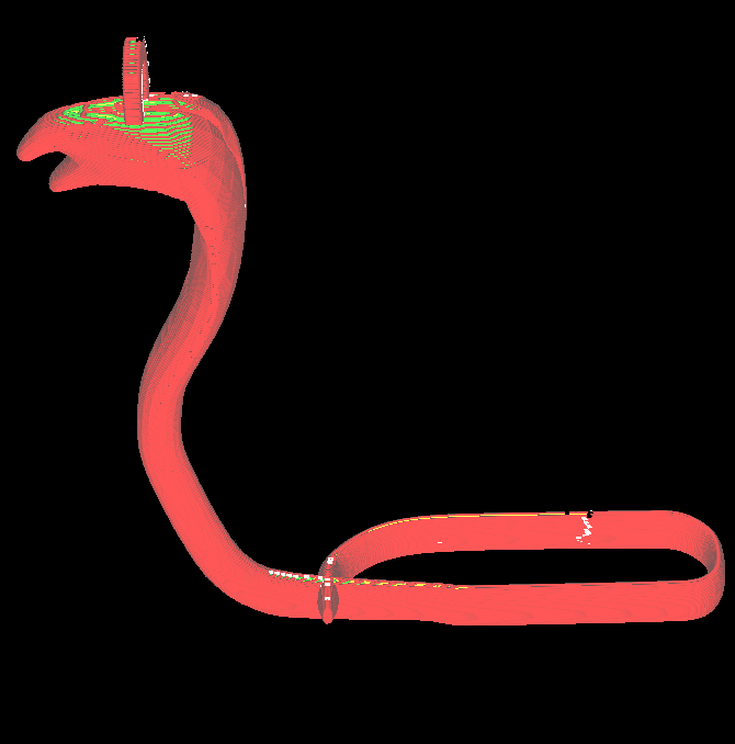
When a 3D printer prints a model, the model is always printed in layers of filament stacked on top of each other. We can see how objects are printed in layers in the following picture:
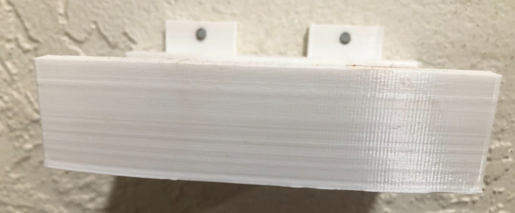
When a slicer software “slices” a model, it not only turns that model into a series of G-code, but it also converts the geometry to hundreds of layers stacked on top of each other, acting as the height of that model. Each layer within that model has a series of movements the nozzle has to make in order to extrude filament in the correct places, to make the correct shapes.
After a slicer software converts the model into G-code, the G-code file must then be inputed into the 3D printer. This can be done wirelessly or through a cord. Once the G-code file is sent, you can chose which file to print from the printer. When you select a specific file to print, the 3D printer will read that file’s G-code and follow the instructions, making the correct movements to print the desired shape.
Example Slicer Software
While CAD software varies extremely in the tools and capability between different pieces of software, all common slicer software share most of the same features and capabilities. A CAD software requires lots of different tools and features because of the infinite different model possibilities. However, a slicer software only requires a few features to convert the CAD file into g-code, while also displaying statistics like print time, filament used, as well as choices of changing settings like infill, layer width, and more.
Ultimaker Cura
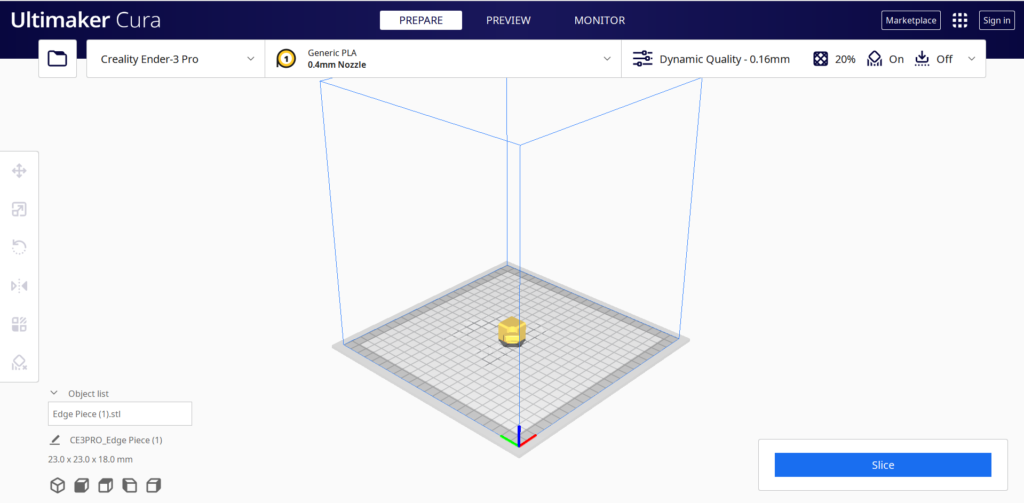
Cura, a 3D printing slicer software made by Ultimaker, is one of the most commonly used programs for converting models into G-code. It allows many different CAD formats outside of STL, STEP, and OBJ to be inputed, including X3D, 3MF, BMP, GIF, JPG, PNG, and more.
While the workspace of a CAD software can be very complicated, Cura has a very simple working environment, making it a popular choice for 3D printer enthusiasts. Along with the default tools and features, Cura also has an online marketplace for plugins and extra features that users can install.
PrusaSlicer
PrusaSlicer, created by Prusa Research, a 3D printer company, is also one of the most commonly used slicer programs for 3D printing. Similarly to Cura, PrusaSlicer is can slice many different file formats outside of the main netural files types.
While the workspace environment of PrusaSlicer is very different from the environment of Cura, it is still a very simple and straightforward working enironment. Both Cura and PrusaSlicer are made by companies that manufacture 3D printers. However, both of these slicer programs are accessible with any 3D printer, not just the ones they produce.
Features of Slicer Software
The main purpose of slicer software is to convert a 3D geometric model into g-code instructions for a 3D printer to read. Apart from doing this, however, there are many other features that Cura, PrusaSlicer, and many other slicer programs possess.
One important feature that most slicer programs include is the ability to customize print settings and options. This means users can change different settings to change how a print is printed.
Changing Infill

One of these preferences includes allowing the user to customize the amount of infill the print will have. Infill is essentially how hollow a print will be. 100% infill means that a print is completely solid on the inside. This would mean that the print is very strong and sturdy, however, this is not recommended for most prints because it will take much more time and filament to print.
Similarly, having infill that’s too low could make a print very fragile. 0% infill means that a print is completely hollow on the inside of the walls. Because the inside of the prints walls are completely hollow, the print would break very easily. However, the print would be significantly faster and use less filament.
This is why customizing the amount of infill in a print is important. Some prints need to be fast and need to use less filament. Other prints need to be very strong and secure to ensure it doesn’t break. Each case requires a different amount of infill. Depending on the purpose of the print, users must decide how much infill they should use, and they can change the amount of infill needed in the slicer software.
Changing Layer Width and Height
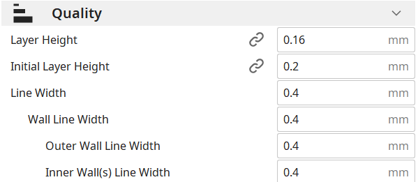
When using slicer software, users also have the ability to customize the layer width and height of the model. When an object is printed, it is printed by stacking layers of filament on top of each other hundreds of times.
Changing layer height directly affects the width of the filament that comes out of the nozzle. Increasing the layer heigh makes a print faster because less layers will be used to print the object. However, larger print layers are also more noticible in the final print.
Decreasing the layer height would make the print quality better, as layers would be less visible and the model would be smoother. However, decreasing the layer heigh also makes it so that more layers are needed to print the model. With more layers in the model, the print process will be much slower.
Similarly to infill, different prints may benefit more from different layer heights and widths. Some prints need to be printed fast, and for those prints a higher layer height and width would be more beneficial. Other prints require more quality over time saved. For those prints, a lower layer height and width would be more favorable.
Summary
Slicer software is a vital tool when 3D printing objects. By converting 3D CAD models into g-code, it enables 3D printers to easily read and follow the instructions of the g-code file. As 3D printing technology continues to evolve, slicer software will remain a key component in the 3D printing process, as it bridges the gap between a 3D computer model, and a physical 3D printed object.
